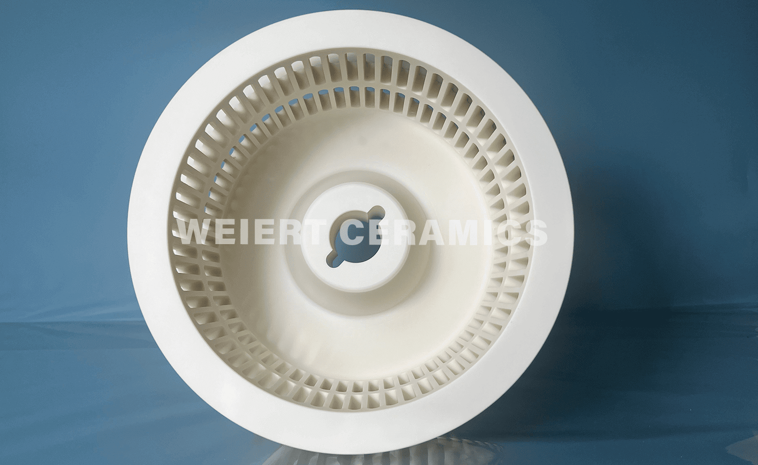
Technologia klasyfikacji ultradrobnych proszków precyzyjnie oddziela mikronowe cząstki według rozmiaru przy użyciu specjalistycznego sprzętu. Jest szeroko stosowana do niemetalicznych ultradrobnych proszków i innych materiałów w takich gałęziach przemysłu, jak elektronika, zaawansowana ceramika i powłoki wysokotemperaturowe.
Klasyfikator powietrzny jest niezbędną częścią do przetwarzania ultradrobnych proszków. Jego główne komponenty obejmują wlot, wlot powietrza, wylot, korpus stożkowy, komorę klasyfikacyjną i silnik. Zasada działania opiera się na regulowanej prędkości obrotowej koła klasyfikatora, które generuje siłę odśrodkową i oddziałuje z przepływem powietrza wpadającym przez wlot powietrza. Siły te wpływają na ruch cząstek o różnych rozmiarach w komorze klasyfikacyjnej, osiągając wysoce dokładną separację wielkości cząstek.
Koło klasyfikatoras jest dotychczasowy niezbędny składniks dla klasyfikator powietrzas i jest zazwyczaj wykonane z materiałów metalowych lub niemetalowych. Do zastosowań, w których należy unikać zanieczyszczeń magnetycznych, zazwyczaj stosuje się koła klasyfikacyjne niemetalowe, wykonane z zaawansowanej ceramiki, takiej jak tlenek cyrkonu, tlenek glinu lub węglik krzemu.
Wytworzenie zintegrowanego ceramicznego koła klasyfikacyjnego wiąże się z dwoma głównymi wyzwaniami: spiekaniem i obróbką CNC. Na koniec musimy upewnić się, że koło przejdzie testy wyważenia dynamicznego nawet przy prędkościach do 6,000 obr./min., tak aby mogło zachować stabilną i wydajną pracę podczas rzeczywistego użytkowania.
Rozkład linii prądu wewnątrz komory klasyfikacyjnej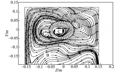
Obraz dodatkowo ilustruje rozkład linii prądu gazu w przekroju podłużnym komory klasyfikacyjnej. Jak pokazano na rysunku, przepływ powietrza tworzy nieregularne poziome wiry wokół koła klasyfikatora. Warto zauważyć, że przepływ powietrza w zewnętrznej części tego typu koła klasyfikatora płynie w tym samym kierunku, co obrót koła, a wzory przepływu wewnątrz i na zewnątrz koła klasyfikatora są spójne.
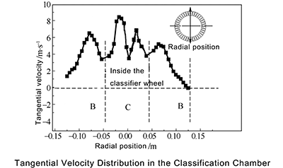
W ultradrobnej klasyfikacji odśrodkowej proszków wielkość prędkości stycznej bezpośrednio wpływa na siłę odśrodkową, której doświadczają cząstki. Rozkład prędkości stycznej w komorze klasyfikacyjnej pokazano na rysunku. W przypadku tego typu klasyfikatora prędkość styczna w komorze klasyfikacyjnej jest całkowicie dodatnia. Gdy przepływ powietrza wchodzi w szczeliny między łopatkami wirnika, prędkość styczna pozostaje stabilna. Zapobiega to rozbieżnościom prędkości stycznej między wewnętrznymi i zewnętrznymi obszarami koła klasyfikatora, unikając w ten sposób nierównomiernego rozkładu pola sił na zewnętrznej krawędzi koła, co w przeciwnym razie zmniejszyłoby wydajność klasyfikacji cząstek.
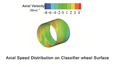
Obraz przedstawia wykres konturowy rozkładu prędkości osiowej na powierzchni cylindrycznej koła klasyfikatora o średnicy zewnętrznej 100 mm. Rozkład prędkości osiowej na powierzchni zewnętrznej koła klasyfikatora dla tego klasyfikatora jest stosunkowo jednolity, z wartościami prędkości bliskimi zeru w większości obszarów. Jakakolwiek obecność prędkości osiowej doprowadziłaby do wahań prędkości przepływu powietrza, co jest szkodliwe dla utrzymania stabilnego pola przepływu i negatywnie wpłynęłoby na dokładność klasyfikacji.
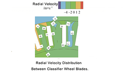
Na obrazie przedstawiono wykres konturowy rozkładu prędkości radialnej przepływu powietrza między łopatkami koła klasyfikatora, gdzie symbol „-” oznacza gaz płynący w kierunku środka wirnika. Na podstawie obrazu można zauważyć, że prędkość radialna między łopatkami tego koła klasyfikatora zmienia się w zakresie -2~1m/s, przy czym rozkład prędkości jest stosunkowo równomierny.
TECHNOLOGIA WEIERT CERAMICS to bezpośredni producent ceramiki technicznej w Chinach — nie pośrednik handlowy. Dostarczamy wysokowydajne komponenty ceramiczne producentom sprzętu do przetwarzania proszków i zapewniamy bezpośrednie rozwiązania użytkownikom końcowym tych systemów.
Mając blisko 10-letnie doświadczenie w produkcji ceramiki technicznej, jesteśmy przekonani o naszej zdolności dostarczania wysokiej jakości, dostosowanych do potrzeb klientów kół klasyfikacyjnych ceramicznych i innych produktów ceramicznych technicznych. Jeśli szukasz niezawodnego partnera w zakresie rozwiązań ceramicznych, skontaktuj się z nami już teraz! Jestem pewien, że nasze konkurencyjne ceny wywołają u Ciebie szeroki uśmiech!
Bibliografia:
[1] SHAPIRO M, GALPERIN V. Klasyfikacja cząstek stałych w powietrzu: a recenzja[J].Inżynieria chemiczna i przetwórstwo, 2005, 44(2):279-285.
[2] XU N, LI G, HUANG Z. Symulacja numeryczna ruchu cząstek w turbo classifier[J].China Particuology,2005,3(5):275-278.
[3] 2016,22(2):82-85.DANG D, WANG KJ. Wpływ prędkości koła klasyfikatora na cząstkę rozkład wielkości [J], China Powder Science and Technology, 2016,22(2):82-85.
[4] 2015, 66(s1):159-164. DANG D, WANG KJ.Wpływ szybkości podawania na pole przepływu wewnątrz klasyfikator[J].Czasopismo przemysłu chemicznego i inżynierii (Chiny), 2015,66(s1):159-164.
[5] TONEVA P, EPPLE P, BREUER M i in. Szlifowanie w powietrzu młyn klasyfikacyjny — Część I: Charakterystyka młyna jednofazowego flow[J].Powder Technology,2011,211(1):19-27.
[6] TONEVA P, WIRTH KE, PEUKERT W. Mielenie w klasyfikatorze powietrznym młyn—część II: Charakterystyka przepływu dwufazowego[J], proszek Technology,2011,211(1):28-37.
[7] JIANG SZ, GE XL, WANG JX. Badanie pola przepływu w układzie poziomym turbo classifier[J].Non-Metallic Mines,1999,22(3):35-37.
[8] WANG X, GE X, ZHAO X i in. Badanie turbiny poziomej classification[J].Powder Technology,1999,102(2):166-170.
[9] LIU D, SONG Y. Badanie eksperymentalne struktury tarczy prowadzącej FJJ klasyfikator wirowy modelowy[J].Siarka, fosfor i materiały sypkie Handling Related Engineering,2012,111(6):13-15.
[10] SUN ZP, SUN GG, XU J. Wpływ deflektora na klasyfikację wydajność poziomego klasyfikatora turbo [J].China Powder Science And Technology,2016,22(1):6-10.
[11] BAUDER A, MÜLLER F, POLKE R. Śledztwa dotyczące mechanizm separacji w klasyfikatorach z kołem deflektorowym[J].Międzynarodowy Czasopismo przetwarzania minerałów, 2004, 74: S147-S154.
[12] REN WJ, LIU JX, YU Y. Projekt klatki wirnika z łukiem niepromieniowym ostrza do turboklasyfikatorów powietrznych[J].Powder Technology,2016,292:46-53.
[13] YUE DX, DIAO X, LI SY i in. Obliczanie rozmiaru przekroju klasyfikatora na podstawie analizy śladów cząstek[J].Przemysł chemiczny i Engineering Progress,2012,31(9):1919-1925.
[14] TONG C, LI SY, LI X. Symulacja numeryczna cząstek trajektoria klasyfikacji wykorzystująca śledzenie niestacjonarne [J].Przemysł chemiczny and Engineering Progress,2013,32(9):2061-2067.
